Set Horizontal Frequency
While booting press the “GRAPH” key and:
- “1” for 24 kHz
- “2” for 31 kHz
Note, not all hardware supports this.
DIP Switches
Bios DIPs
The PC-9821 uses soft dips. To access, turn on the power or press the reset button and then press the “HELP” key. To reset software dips press RESET + [GRPH] + [SHIFT].
The following DIP settings were translated at retrostuff.org and I have copied them here in the case that the site disappears one day.
For most DOS games use:
- Switch 2 settings:
- GDC Clock: 2.5MHz
- Switch 3 settings:
- Floppy Disk Mode: Automatic (640K)
Keyboard Actions
| Keys | Action |
| Up/Down | Select |
| Left/Right | Set |
| Home CLR | Factory settings |
| Esc | Back to main menu |
DIP Switch 1 Settings
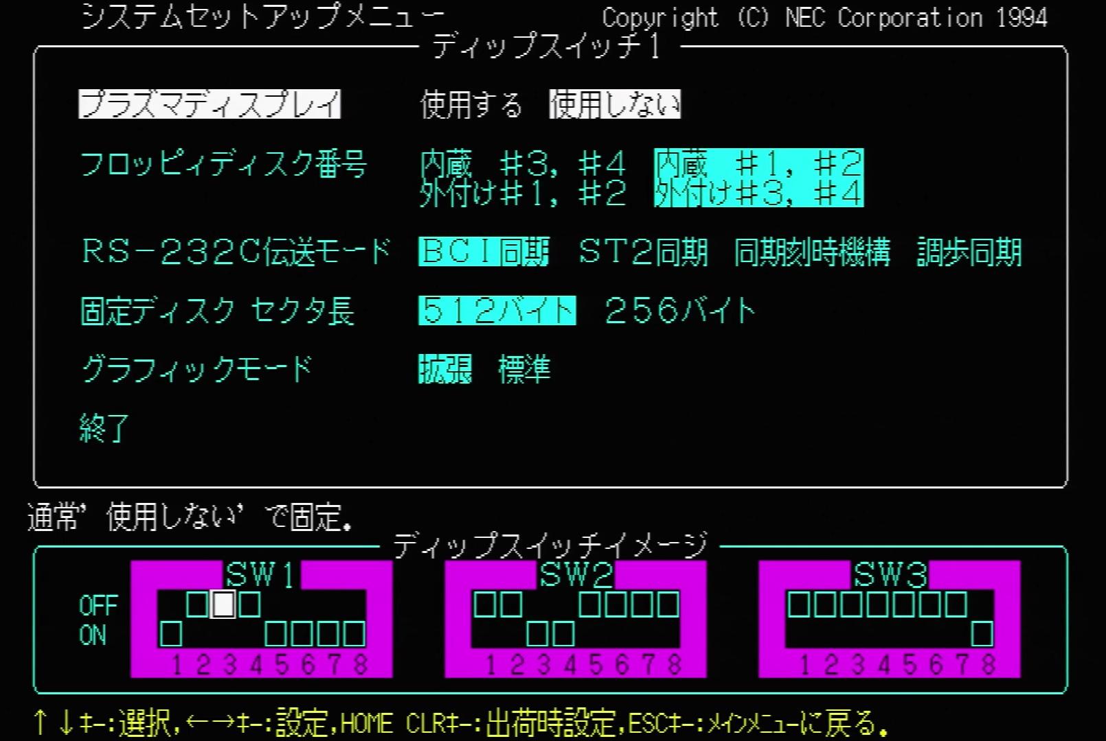
| Settings | Options |
| Plasma Display | – Enabled – Disabled Hint: Usually disabled |
| Floppy Disk Sequence | – Internal #3, #4 | External #1, #2 (prioritize ext FDD) – Internal #1, #2 | External #3, #4 (prioritize int FDD) |
| RS-232C Transmission Mode | – BCI Sync (use internal clock for transmission, use modem clock for reception) – ST2 Sync (use modem clock for transmission and reception) – Sync Clock (use clock signal created from received data for reception, use internal clock for transmission) – Asynchronous (use internal clock for transmission and reception |
| Hard Disk Sector Size | – 512 bytes – 256 bytes |
| Graphics Mode | – Enhanced (16 out of 4096 colors) – Standard (8 out of 8 colors) |
DIP Switch 2 Settings

| Settings | Options |
| Terminal Mode Specification | – Terminal Mode (Start BASIC in terminal mode) – BASIC Mode (Start BASIC in BASIC mode) |
| Lines of Text per Screen | – 25 lines/screen (Display 25 lines of text per screen) – 20 lines/screen (Display 20 lines of text per screen) |
| Memory Switch | – Keep (Keep the contents of memory switch at startup) – Initialize (Initialize the contents of memory switch at startup) |
| Internal Hard Disk | – Disabled (Disable internal hard disk) – Enabled (Enable internal hard disk) |
| GDC Clock | – 5MHz (Operate GDC with 5MHz clock) – 2.5Mhz (Operate GDC with 2.5MHz clock) |
DIP Switch 3 Settings
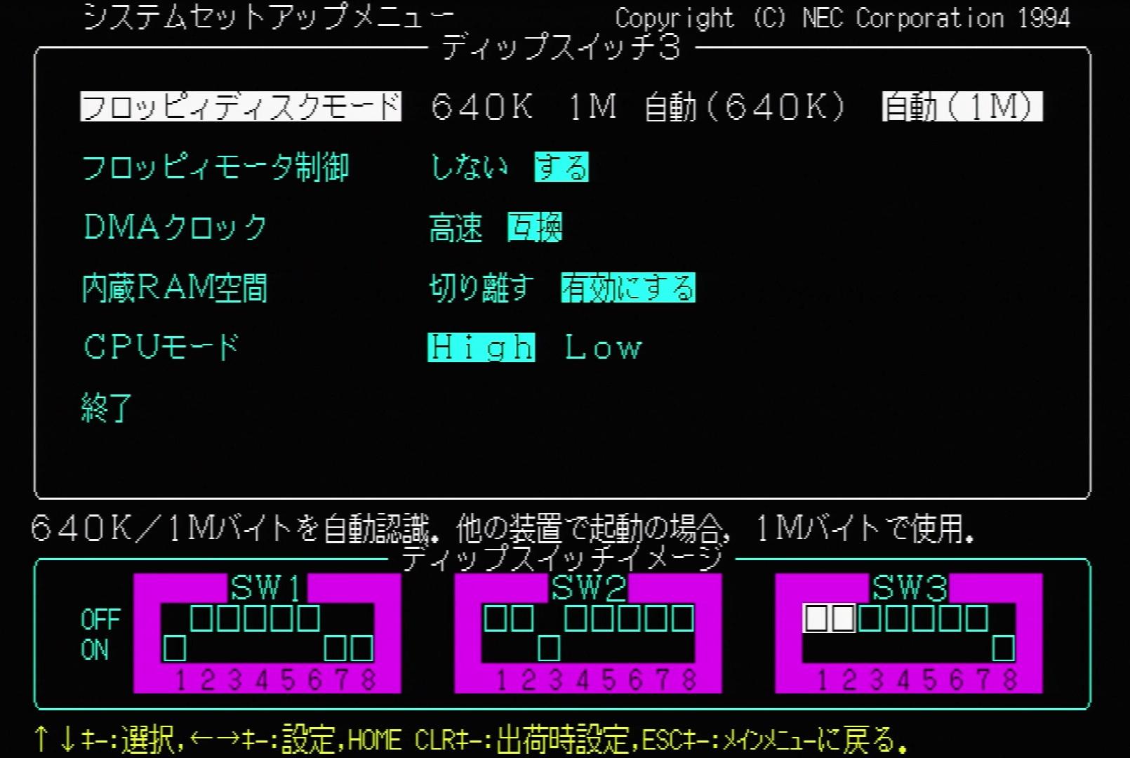
| Setting | Options |
| Floppy Disk Mode | – 640K (Use internal FDD with 640Kbyte fixed) – 1M (Use internal FDD with 1Mbyte fixed) – Automatic (640K) (Automatic recognition of 640K/1M. Use 640K when starting another device) – Automatic (1M) (Automatic recognition of 640K/1M. Use 1M when starting another device) |
| Floppy Motor Control | – Disable (Do not control floppy disk motor) – Enable (Stop floppy disk motor if no access for 15 seconds) |
| DMA Clock | – High Speed – Compatible |
| Internal RAM Hole | – Disabled (Disable memory hold at 512K-640K) – Enabled (Enable memory hold at 512K-640K) |
| CPU Mode | – High (Start in High mode) – Low (Start in Low mode) |
Operating Environment Settings

| Setting | Options |
| 16MB Memory Hole | – Disabled (The system does not use memory hold at 15M-16M) – Enabled (The system uses memory hold at 15M-16M) Hint: When using Windows 3.1 please set to “enabled” |
| ROM BASIC | – Do not start ROM BASIC – Start ROM BASIC |
| Speaker Volume | – High – Medium – Low – Off Hint: Set the volume of the internal buzzer |
Hard DIPs
Apart from this, there are two switches in the cover on the front of the main unit. Each one is as follows. The pink highlight is the default.
Switching CPU Operating Speed (left side)
| Display | Power Lamp | Operating Speed |
| H | green | i486DX2 66MHz |
| M | yellow | i486SX equivalent to 16MHz |
| L | red | V30 equivalent to 8MHz |
Note:
- In V30 emulation mode, all memory larger than 640KB is ignored and fixed at 640KB. Note that software and expansion boards that require V30 may not work properly because they are not 100% completely compatible.
- Also, if the operating mode is set to high resolution mode, V30 emulation mode can not be selected regardless of the presence of the 98 high resolution board.
Switching Operation Mode (right side)
| Display | Action Mode |
| N | Normal mode |
| H | High res mode (selectable when equipped with 98 high res board) |
Note:
- If the high resolution mode is set to the high resolution side without the 98 high resolution board, problems will occur in switching the operating speed, so be sure to set it to the normal side.
Window Accelerator Board A (PC-9821A-E01)
| Switch Number | Function | On | Off |
| 1 | CRT display operation method | Non-interlaced | Interlaced |
| 2 | Not used (always on) | – | – |
| 3 | Not used (always on) | – | – |
| 4 | Not used (always on) | – | – |
| 5 | CPU address space setting | ON, ON: F00000h to F0FFFFh, F80000h to F80FFFh ON, OFF: F20000h to F2FFFFh, F88000h to F88FFFh OFF, ON: F40000h to F4FFFFh, F90000h to F90FFFh OFF, OFF: F60000h to F6FFFFh, F98000h to F98Fha | |
| 6 | |||
| 7 | Not used (always on) | – | – |
| 8 | Not used (always on) | – | – |
Open Source Scan Converter (OSSC)
Optimal Timings
| Console / mode | Dots per scanline / no. scanlines / @dotclk | OSSC base mode | Modified parameters |
| PC-98 640×400 @56.4Hz | 848 / 440 / @21.0526MHz | 640×400 | H.samplerate=848 H.synclen=64 H.backporch=80 V.backporch=32 |
More PC-98 OSSC Links:
- https://www.videogameperfection.com/forums/topic/pc-98-to-tv-support/
- http://junkerhq.net/xrgb/index.php?title=Optimal_timings
Write a Floppy from an Image on Real Hardware
Prerequisites
- You need Mahalito on your PC-98 hard drive to write an image
- Your image must be in Mahalito format so you will likely need to use Virtual Floppy Image Converter.
Process
- Convert your floppy disk image (.fdi, .hdm, etc) to Mahalito format using Virtual Floppy Image Converter.
- Transfer the Mahalito formatted image to your PC-98
- Transfer the Mahalito program to your PC-98 as well
- Insert a floppy into your drive
- Format the floppy if you haven’t using:
FORMAT b: /M
- Write the image to the floppy using:
mahalito e FLOPPY_IMG b:- You will have two files so FLOPPY_IMG should be the name without extension. Ex: if you have DISK1.2HD and DISK1.DAT use DISK1 for FLOPPY_IMG.
Software Shortcuts
FILMTN
- Change path:
- Press ‘L’
SEDIT
- Save file:
- Press ‘F1’ then ‘S’
- Quit:
- Press ‘F1’ then ‘Q’
- Save and Exit:
- Press ‘F1’ then ‘E’